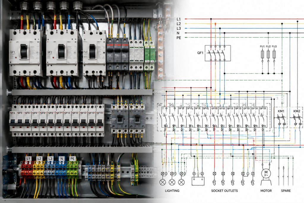
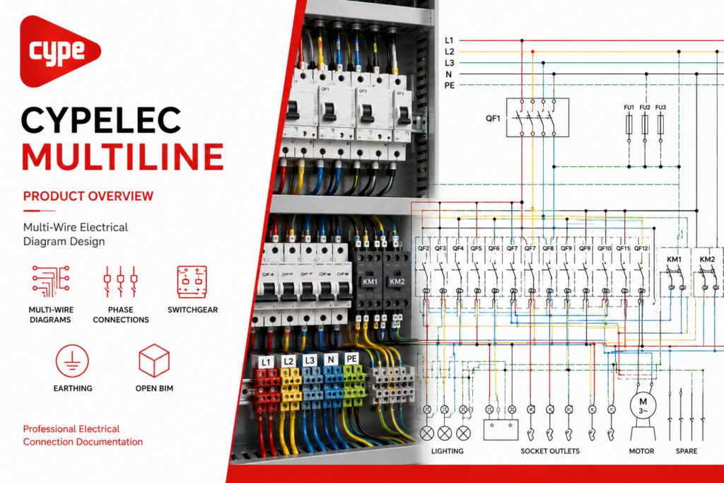
Electrical documentation software for automatically generating and editing detailed multi-wire diagrams from low-voltage installations designed in CYPELEC.
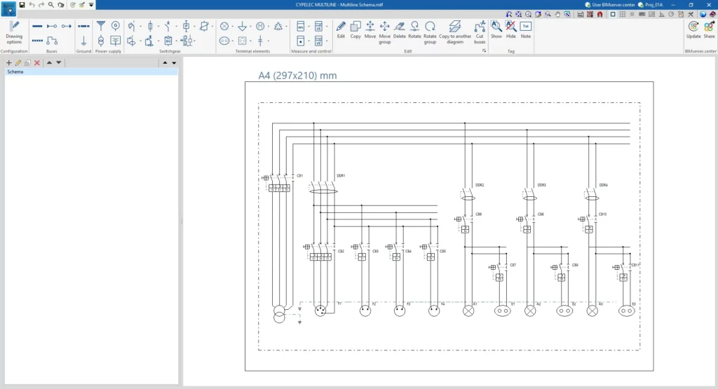
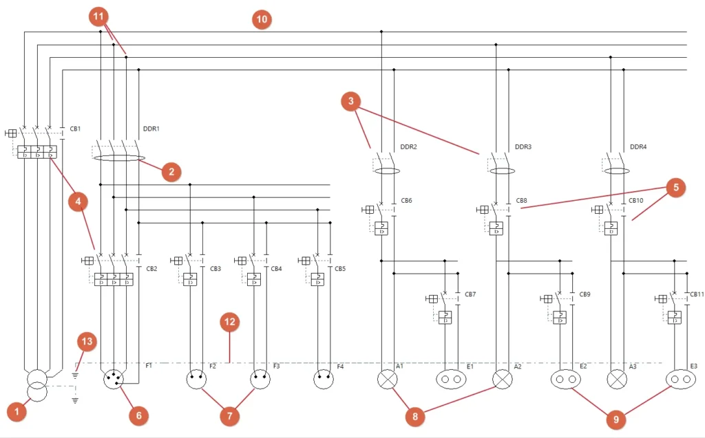
CYPELEC MULTILINE creates detailed multi-wire diagrams for electrical installations, representing individual conductors, protection devices, buses, earthing elements and terminal loads. Diagrams can be created manually or automatically generated from phased low-voltage systems designed in CYPELEC, helping engineers move from preliminary electrical design toward detailed installation and connection documentation.
Overview
CYPELEC MULTILINE is designed to create detailed multi-wire diagrams for low-voltage electrical installations. Unlike a single-line diagram, it represents individual conductors and their connections to buses, protection devices, terminal equipment, measurement elements and earthing systems.
Diagrams can be developed manually or generated automatically using installation information imported from CYPELEC, including switchboard structure and phase connections for single-phase and three-phase circuits. The generated diagrams remain fully editable.
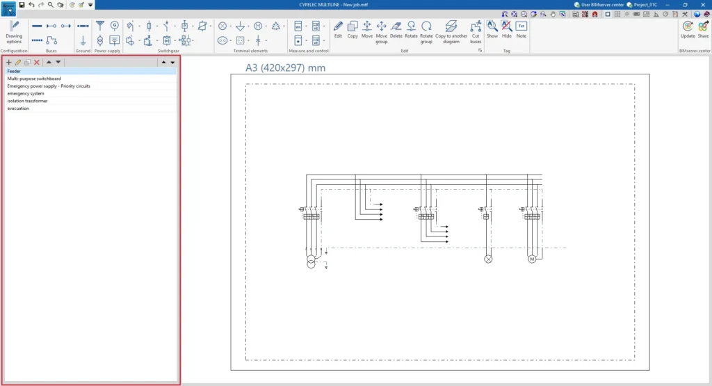
Completed drawings can be organised across multiple sheets and exported to DXF, DWG or PDF, while BIMserver.center allows the resulting project information to be shared with other project participants.
Applications
Multi-wire diagram generation
Phase connection representation
Switchgear documentation
Busbar connections
Earthing diagrams
Terminal element wiring
Electrical connection detailing
Multi-sheet drawings
CYPELEC data import
Open BIM collaboration
Product Resources
Watch the official product video or download the technical datasheet for more detailed information.